


RS-232 remote control for video switch
The projector in our church is set up so that we can display a number of different video sources. Each source (laptop, DVD player, VCR) is wired into a Kramer VP-719DS video switcher/scaler unit in our sound cabinet, and that outputs a VGA signal to the projector at the front of the sanctuary.
Because of the location of the switcher/scaler unit, it is the sound operator's responsibility to make sure that the correct video source is selected. This project makes it possible for the laptop operator to control the switcher/scaler unit as well.
Design features:
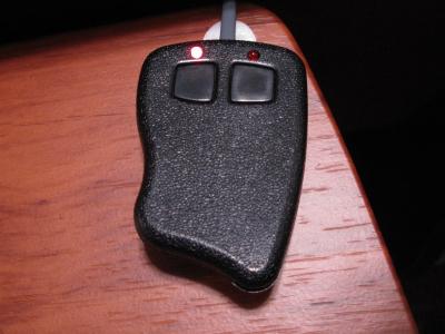
- Small keyfob-style enclosure with two buttons and two indicator LEDs
- Left button sets video source to laptop
- Right button blacks out the video display
- Two taps on the left button freezes the video display
- Communicates with a Kramer video switcher/scaler unit using the RS-232 serial protocol
- No external power supply necessary
Construction
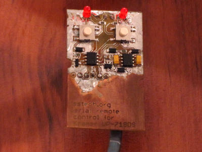
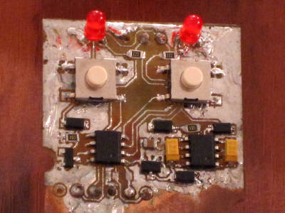
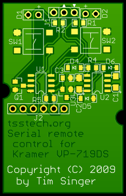
The circuit is etched on a single-layer PCB cut to fit into a keyfob enclosure. I exposed a presensitized board (coated with photoresist) using a fluorescent light box and laser-printed overhead transparencies for the circuit pattern.
The components are hand-soldered onto the PCB using a small 12W needle-tip iron. I applied a solder coating to all of the traces and ground plane areas around the components in order to keep the copper from corroding.
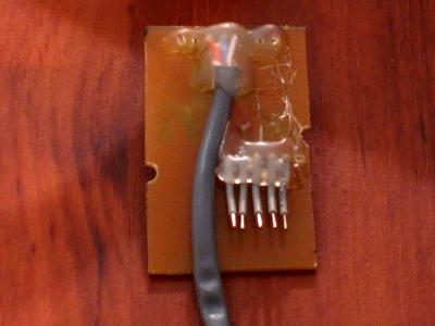
The cable wraps around the board lengthwise. I used solid-core wire for the cable because I had some on hand, but stranded wire would have been a better choice.
Five short pieces of wire underneath the board make up the programming header. Hot glue serves as strain relief so that the wires and serial cable don't break the solder joints or rip the pads off of the board.
Project status
The project is complete, and has been installed and operating in the church for a few weeks as of November 2009.
Bill of materials
| C1,C2 - | Charge pump capacitors: | 10µF, ≥25V | (3216 metric) | Any appropriate |
| C3 - | Stabilizing capacitor: | 1µF | (0805) | Any appropriate |
| D1,D2 - | Indicator LEDs: | Red, high-efficiency | (T-1) | Kingbright WP7104LSRD |
| D4-D5 - | Signal rectifier diodes: | Schottky, VR≥30V | (SOD-123) | ON Semiconductor BAT54T1G |
| D6 - | Charge pump start-up diode: | Schottky, VR≥15V | (SOD-123) | ON Semiconductor BAT54T1G |
| J1 - | RS-232 header: | (Solder 3-conductor cable to these pads) | ||
| J2 - | Programming header: | (Not placed - program the microcontroller by holding a free-hanging male header in these holes) | ||
| R1,R2 - | Current-limiting resistors for red LEDs: | 2.2kΩ | (0805) | Any appropriate |
| R4 - | Charge pump start-up pull-down resistor: | 1MΩ | (0805) | Any appropriate |
| R5 - | (Not placed) MCLR pull-up resistor: | 10kΩ | (0805) | Any appropriate |
| Q1 - | Transistor for RS-232 receive signal: | N-channel MOSFET, small signal, VGS≥15V | (SOT23) | ON Semiconductor 2N7002ET1G |
| U1 - | Microcontroller: | 8-bit PIC, 1MIPS | (SOIC-8) | Microchip PIC12F509 |
| U2 - | Charge pump voltage doubler: | -12V input | (SOIC-8) | Microchip TC1044SEOA |
| U3 - | Voltage regulator: | +12V input, 5V output, LDO | (SOT23A) | Microchip MCP1702T-5002E/CB |
| N/A - | Enclosure: | Key fob, 2 buttons | Serpac CA-4, 2 BLACK | |
| N/A - | RS-232 cable: | 3-conductor stranded, 10' long | [Spare cable] | |
| N/A - | D-sub connector: | Solder cup | (DE9/DB9) | Norcomp 171-009-203L001 |
| N/A - | Backshell hood: | Plastic backshell hood | (DE9/DB9) | Norcomp 977-009-010R031 |
| N/A - | PCB: | Single-layer, presensitized, at least 1.5"×2" (or special order) | Any appropriate | |
Design files
IMPORTANT: Please measure the RS-232 signal voltage before connecting this circuit. The power supply can only support up to 12 volts on the RS-232 signal lines, and some serial ports may put out as much as 15 volts.
These design files are for the updated version where I have removed two of the unnecessary components.
The board is single-sided with no jumper wires, so you can etch it in your garage for minimal cost if you've already got the chemicals and equipment.
Design details
Power supply
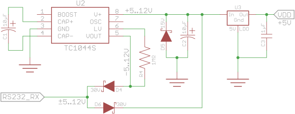
The outgoing signal line on a typical RS-232 serial port can supply a few milliamps of current somewhere between 3 and 15 volts. The signal wire is usually negative with respect to the ground pin, but swings positive when there's a zero bit on the line. The switcher/scaler unit that I'm dealing with sometimes outputs just over 5V with no load, and sometimes outputs up to 8V.
In order to get +5V power supply to the microcontroller and keep the same ground reference, first D4 rectifies the RS-232 signal to a negative voltage. U2 then doubles the voltage difference between the negative supply and ground to generate a positive supply, then U3 regulates the positive supply down to +5V. The PIC doesn't pull that much current at all, and the LEDs I've chosen light acceptably at just 1.5mA.
D5 and R4 are necessary to start up U2's internal switching circuitry, as per the TC1044S datasheet.
In order to keep the power supply to the PIC consistent, D6 bypasses the voltage doubler when the RS-232 signal swings positive.
Transmitting commands to the switcher/scaler unit
To transmit data to the switcher/scaler unit, I just have the signal line tied to an output pin on the PIC. Even though 0V is not a valid signal state for RS-232, the swing between 0 and +4.8V is enough for the unit to correctly receive the serial data.

Receiving responses from the switcher/scaler unit
To receive data from the switcher/scaler unit, I have to translate the ±3..15V RS-232 signal to logic levels (0..5V. To do that, I use a MOSFET to serve as an open-collector output, attached to one of the input pins on the PIC, which has internal pull-up resistors.
Originally, I also included a rectifier diode D3 and a pull-down resistor R3 for the gate, but as it turns out, those components are not necessary because the gate can handle ±20V.
PIC peripherals used
- GPIO inputs with internal pull-up resistors - RS-232 rx line, buttons
- GPIO outputs - RS-232 tx line, indicator LEDs
- Timer0 - Periodic status poll timer, double-click detection, RS-232 receive timeout
Component selection
Note: I follow the rules of significant figures for these calculations. Be careful about the unit magnitudes (kilo-, nano-, etc.) during multiplication and division.
C1,C2,R4 - Charge pump components
The values for the charge pump capacitors and resistor were taken from the voltage doubler datasheet. They need to be able to handle at least 15V, and probably should be at least 20V. Tantalum capacitors have the smallest footprint for the best low-volume price that I found. If you are buying more than five capacitors, the 1206 ceramic type, which is cheaper in volume, should also work.
C3 - Stabilizing capacitor for voltage regulator
The value for this capacitor was taken from the LDO voltage regulator datasheet.
D4,D5,D6
The diodes need to handle a voltage difference of at least 30V when connected between the positive and negative supply buses, or 15V when connected between a supply bus and the signal ground.
R1,R2 - Current-limiting resistors for red LEDs
Conditions
| Desired current to light the LED: | ILED = 1.5mA |
| Supply voltage from the PIC: | VCC = 5.0V |
| Forward voltage drop for LED: | VF = 1.7V |
Equations
| Calculating resistance (Ohm's Law): | V = I • R |
| Calculating power (watts): | P = V • I |
Resistor value
| Voltage drop across the resistor: | VRES = VCC − VF = 5.0V − 1.7V = 3.3V | |||||||
| Resistor value from Ohm's Law: |
|
Minimum power rating
| Power in milliwatts: | P = VRES • ILED = 3.3V • 1.5mA = 5.0mW |
Firmware components
The firmware has a few reusable algorithms:
- Simple cycle-accurate delay loops
- RS-232 single-byte transmit procedure (9600bps)
- RS-232 single-byte receive procedure (9600bps)
- Double-click detection
Even though it was developed for the PIC12F509, the code and data footprint is small enough to fit on the PIC12F508.
Possible refinements
Since making this device, I've recognized a few changes I could have made to safe a few cents or make it more compliant with the RS-232 specification:
- The firmware could easily be ported to the PIC12F508 to save a few pennies.
- Since only one of the LEDs is on at any time, they could use a common current-limiting resistor on the cathode end. It might necessitate a jumper wire or a second copper layer on the board, though.
- It may be possible to replace the charge pump voltage doubler with one that can handle a 15V input. The circuit would need to be rearranged.
- A second MOSFET, and perhaps another resistor and capacitor could possibly be used to send a valid RS-232 negative voltage instead of 0V when idle.