


Wireless Projector Remote
A few years ago, we installed a projector in the church sanctuary. It is mounted to the front of an exposed truss, and the laptop that controls the video display is in the back of the sanctuary. The problem is that to turn the projector on or off, someone always needed to go to the front of the sanctuary and point the remote at the projector, which is not ideal.
This is my attempt at solving that problem. The idea is that instead of using an infrared signal from the back of the sanctuary, we'd have a key fob RF transmitter that would send a signal to a receiver. The battery-powered receiver would be placed somewhere at the front, pointed at the projector, and would translate the RF signal to the IR on/off remote commands that the projector understands.
Design features:
- 315 MHz on/off-keyed signal
- Low-power receiver powered by 2 AAA batteries (should last several months on one charge)
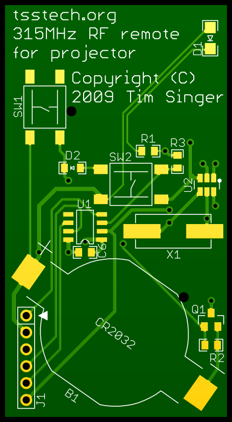
- Key fob transmitter powered by a CR2032 cell
- Separate on and off commands, keyed to two buttons on the transmitter
Project status
The RF transmitter and receiver circuits work to the point where I can get good carrier wave detection at about 30 feet.
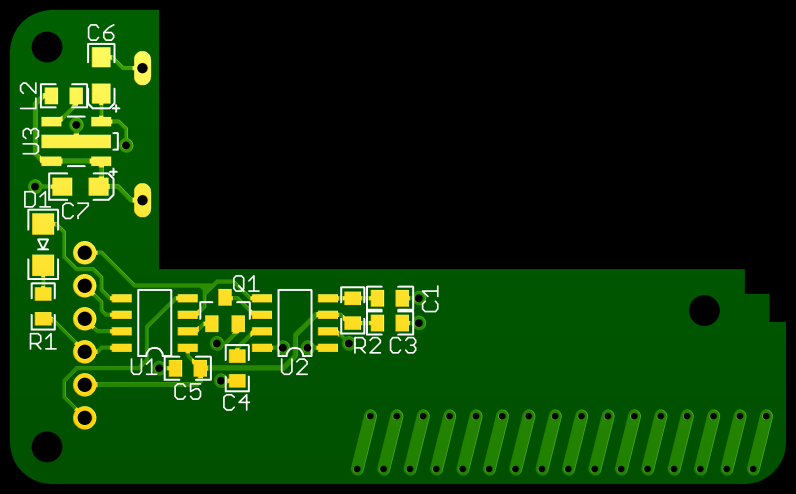
The receiver, however, consumes way too much battery power, because the inductor I used for the boost regulator doesn't have a high enough saturation current. The bill of materials (below) reflects this change in the receiver component L2. I have not resized the land pattern on the board yet - it's still sized for an 0805 component.
The project has since been abandoned, because we now have a new projector with a remote powerful enough to bounce off of the front wall.
Bill of materials
Transmitter:
| B1 - | Coin cell holder: | CR2032 | MPD BU2032SM-HD-G | |
| C1 - | Filter capacitor: | 10µF | (0805) | Any appropriate |
| C2 - | Antenna impedance matching: | 6.8pF | (0805) | Any appropriate |
| C3 - | Antenna impedance matching: | 10pF | (0805) | Any appropriate |
| C4,C5 - | Oscillator capacitors: | 18pF | (0805) | Any appropriate |
| C6 - | Filter capacitor: | 0.1µF | (0805) | Any appropriate |
| D1 - | Activity LED: | 10mA typ., Red | (1206) | Lite-On LTST-C150KRKT |
| D2 - | Power control circuit diode: | Schottky, Vr>5V | (SOD-323) | ON Semiconductor MMDL101T1G |
| L1 - | Antenna impedance matching: | 470nH, SRF>315MHz | (0805) | Any appropriate |
| L2 - | Antenna impedance matching: | 150nH, SRF>315MHz | (0805) | Any appropriate |
| R1 - | Current-limiting resistor for LED: | 120Ω | (0805) | Any appropriate |
| R2,R3 - | Power control pull-down resistors: | 1MΩ | (0805) | Any appropriate |
| SW1,SW2 - | Tactile switches: | 7mm high, 160gf | (6mm) | E-Switch TL3301FF160QG |
| Q1 - | Power control transistor: | N-channel MOSFET, small signal | (SOT23) | NXP 2N7002E,215 |
| U1 - | Microcontroller: | 8-bit PIC | (SOIC-8) | Microchip PIC12F615 |
| U2 - | Transmitter IC: | 315MHz on-off keyed | (SOT23-6) | Micrel MICRF113 |
| X1 - | Oscillator crystal: | 9.84375MHz | (HC49/US) | Abracon ABLS-9.84375MHZ-10-R20-D |
| N/A - | Battery: | 3V, 225mAh | (CR2032) | Panasonic CR2032 |
| N/A - | Keyfob enclosure: | 2 buttons+LED window | Teko 11122.4 |
Receiver:
| B1 - | Battery terminals: | Bent paper clips | N/A | |
| C1 - | RF data slicing capacitor: | 0.033µF | (0805) | Any appropriate |
| C2 - | Antenna impedance matching: | 5.6pF | (0805) | Any appropriate |
| C3,C5 - | Filter capacitors: | 0.1µF | (0805) | Any appropriate |
| C4 - | RF gain control capacitor: | 1µF or 2.2µF | (0805) | Any appropriate |
| C6,C7 - | Boost regulator capacitors: | 22µF, tantalum | (3216 metric) | Any appropriate |
| D1 - | IR LED: | 20mA typ., 880nm | (1206) | TT/Optek OP250 |
| L1 - | Antenna impedance matching: | 56nH, SRF>315MHz | (0805) | Any appropriate |
| L2 - | Boost regulator inductor: | 100µH, >250mA | (1007) | Taiyo Yuden CB2518T101K |
| R1 - | Current-limiting resistor for LED: | 220Ω | (0805) | Any appropriate |
| R2 - | Noise squelch resistor: | 10MΩ or 8.2MΩ | (0805) | Any appropriate |
| Q1 - | Signal inverting transistor: | N-channel MOSFET, small signal | (SOT23) | NXP 2N7002E,215 |
| U1 - | Microcontroller: | 8-bit PIC | (SOIC-8) | Microchip PIC12F615 |
| U2 - | RF Receiver IC: | 315MHz on-off keyed | (SOIC-8) | Micrel MICRF010 |
| U3 - | Boost regulator: | 3V-to-5V boost | (SOT89-5) | NJR NUJ7216U50 |
| X1 - | Oscillator crystal: | 9.7941MHz | (HC49/US) | Abracon ABLS-9.7941MHZ-10-R20-D |
| N/A - | Enclosure: | Battery compartment for two AAA cells | New Age Enclosures S-251605 |
Design files
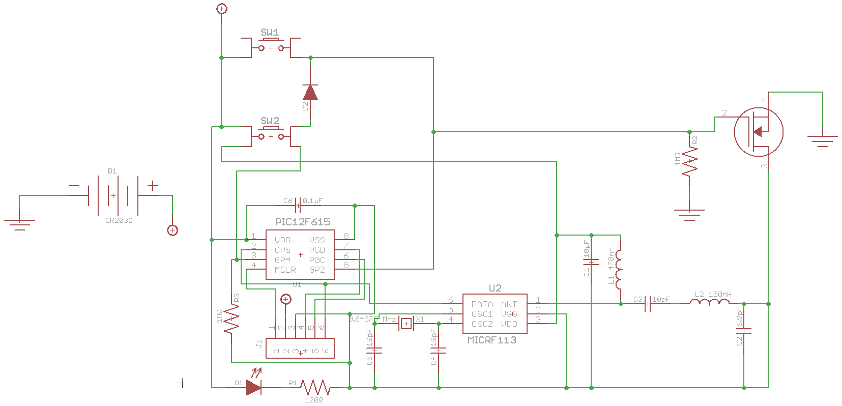
- Transmitter schematic
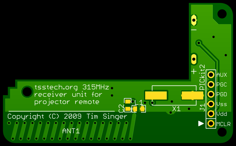
- Receiver schematic
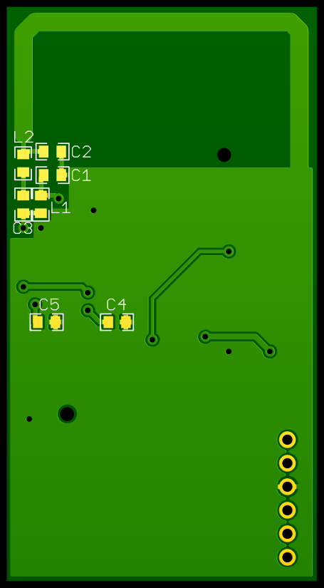
- Eagle design files
- Gerbers
- Source code (8-bit assembly) for testing RF carrier reception
Design details
RF antenna design
This being an RF application, I needed to pay special attention to sizing the various capacitors and inductors used in the RF blocks.
Transmitter antenna impedance matching
On the transmitter, I used the loop antenna from Micrel's example PCB layout. I used Micrel's specified matching network, with no modifications.
Receiver antenna impedance matching
On the receiver, I used Micrel's Heli-2 PCB antenna. For this one, I had to calculate a matching network. Impedance are given as complex numbers, the first component being resistance, and the second (the number prefixed by 'j') being reactance.
- MICRF010 input impedance at 315MHz: 13.48 − j145 (from the MICRF010 datasheet)
- Heli-2 antenna impedance at 315MHz: 11.2 − j216.1 (from Micrel app note 52)
This online tool calculated the following values for an LC network:
- L: 0.05725µH
- C: 5.5pF
Transmitter power supply
Since the transmitter is powered off of a coin cell battery, I didn't want it to be constantly drawing current for the microprocessor (although I could have used the microcontroller's ultra low-power sleep mode and wake-on-change feature for that). I tried to design a system where the ground plane is connected to the negative battery terminal through a MOSFET, which is activated by the buttons, and held active by an output pin on the microcontroller. The idea was that the microcontroller could decide how long to keep the power connected, then shut it off completely once the transmission completes.
Once I put the board together, I measured the off-state current and found that it is not zero. The problem, I surmise, is twofold. First, a small amount of current flows through the pull-down resistor for the MOSFET gate. Second, when the MOSFET is turned off, the ground plane is slowly pulled up toward the positive battery voltage, which also slowly raises the MOSFET gate signal wire, even with the pull-down resistor. The transistor finally reaches a balance point where it is partially on. It works well enough, but I would have been better off using the microcontroller's low-power sleep mode.
Work yet to be done
In order for this project to be workable, a number of things would still need to be done:
- Hardware: Redesign the receiver with a better 3V-to-5V boost circuit.
- Hardware: Redesign the transmitter to use the microcontroller's low-power sleep mode.
- Firmware: Implement Manchester encoding in the transmitter (right now, it just sends alternating on/off signals)
- Firmware: Implement Manchester decoding in the receiver
- Firmware: Implement IR signal transmission in the receiver